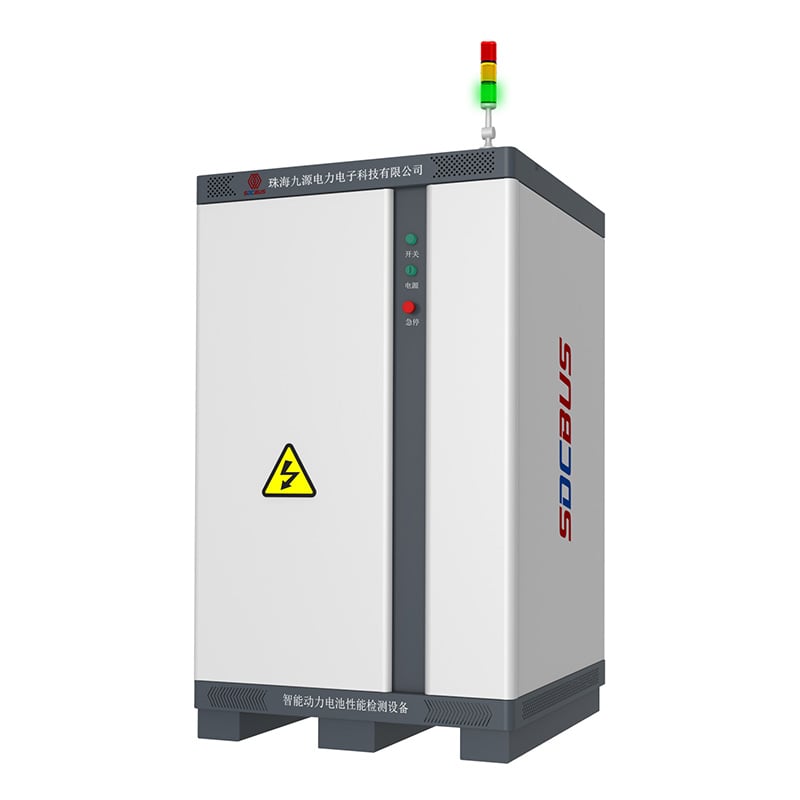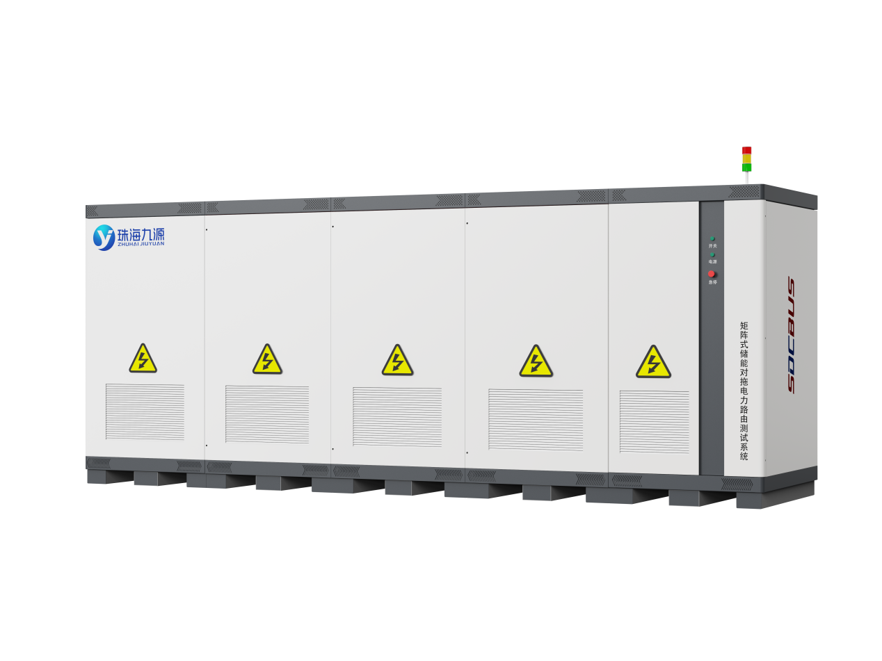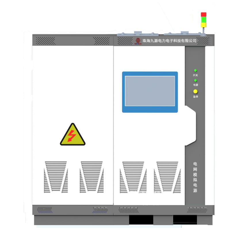
JHT Series Grid Analog Power System
The JHT Series Grid Simulation Power System is a high-precision (voltage accuracy ≤±0.1%, frequency accuracy ≤0.001Hz), high-dynamics (1ms response time), and full-featured power grid simulator. It is designed for grid adaptability testing of converter equipment in energy storage, photovoltaic, and other renewable energy applications. By leveraging advanced digital control technology (supporting software programming and real-time adjustments), the system enables four-quadrant operation (bidirectional energy flow) and simulates grid characteristics ranging from ideal to "extremely harsh conditions". This system addresses critical testing needs of renewable energy converters, including grid-connected impact resistance, harmonic tolerance, and frequency ride-through capabilities.
Application
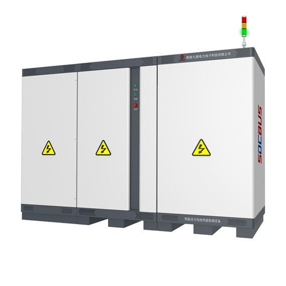
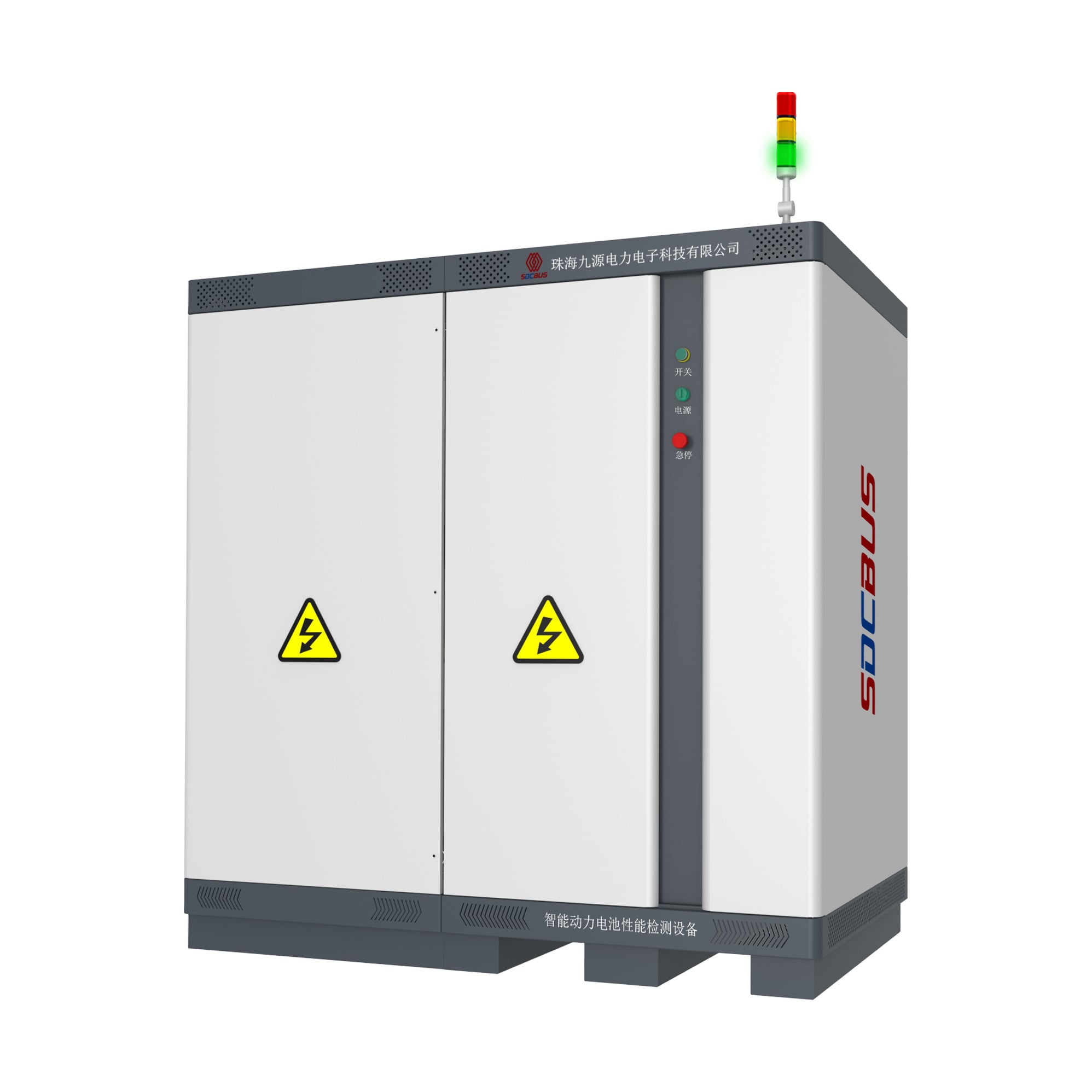
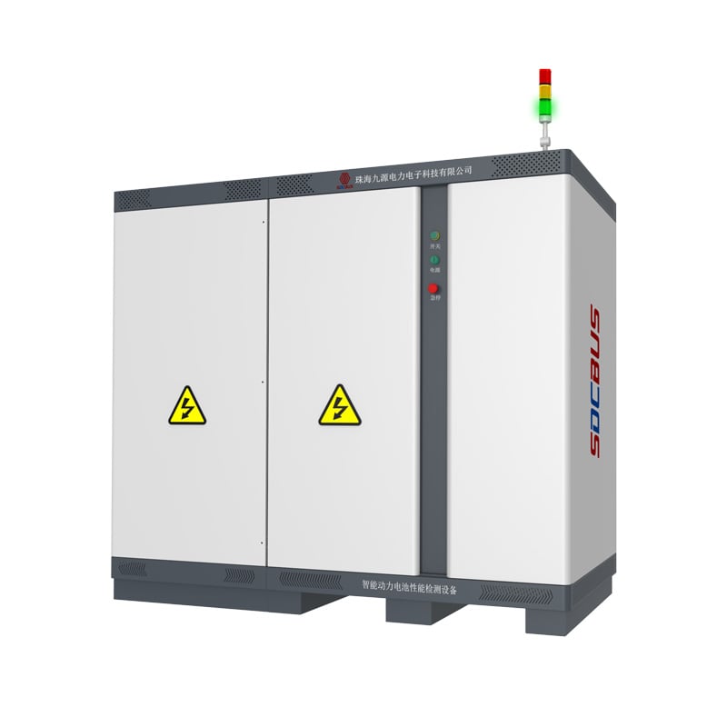
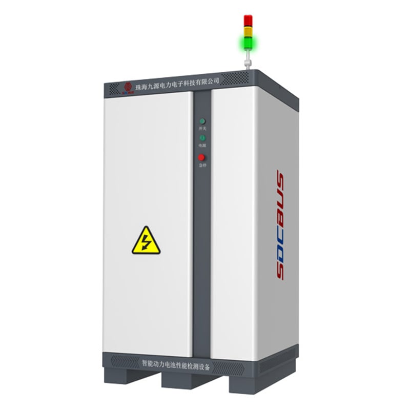
![]()
- Overview
- Recommended Products
Product Features
It supports sine wave and harmonic superposition modes to simulate grid anomalies, including over-voltage/under-voltage, over-frequency/under-frequency, three-phase imbalance, and voltage ride-through conditions.
The bidirectional energy transfer capability reduces energy consumption by up to 90% and lowers operational costs.
32-bit floating-point DSP technology enables fully programmable test sequences with real-time adaptive control.
It supports high/low (zero) voltage ride-through, step changes, voltage sags, flicker testing, and 1ms transient response.
It enables real-time monitoring of critical parameters (e.g., IGBT/transformer temperatures) and 16-bit resolution data recording for predictive maintenance.
It is equipped with CAN2.0A/B, RS485, Ethernet (standard) and optional RS232/GPIB interfaces for flexible integration.
Application
Grid-connected/off-grid performance validation of inverters and PCS; MPPT analysis.
Charging/discharging characteristics and grid compatibility tests of electric vehicle charging stations.
Dynamic response and fault simulation for inverters and UPS systems.
Microgrid stability analysis over grid transitions (e.g., load shifts).
Specification
Typical Device Models
| Model | Rated Power (kVA) | Voltage Range (V) | Frequency (Hz) | Maximum Current/Phase (A) | Weight (kg) | Dimensions (W × D × H / mm) |
|---|---|---|---|---|---|---|
| JHT-063F-4Q | 63 | 0~470 | 40~70 | 150 | 240 | 1000×1000×1500 |
| JHT-100F-4Q | 100 | 0~470 | 40~70 | 200 | 300 | 1000×1000×1500 |
| JHT-150F-4Q | 150 | 0~470 | 40~70 | 400 | 400 | 1000×1000×1900 |
| JHT-240F-4Q | 240 | 0~470 | 40~70 | 450 | 500 | 1140×1000×1900 |
| JHT-320F-4Q | 320 | 0~470 | 40~70 | 500 | 2400 | 1140×1000×1900 |
| JHT-630F-4Q | 630 | 0~900 | 40~70 | 900 | 4500 | 5840×1200×1900 |
| JHT-1000F-4Q | 1000 | 0~900 | 40~70 | 1000 | 6800 | 7840×1200×1900 |
System Parameters | ||||||
| Load-side parameters | Load Output Mode | Three-phase four-wire output; each phase can be output independently | ||||
| Voltage | Line voltage: AC0V~900V | |||||
| Frequency | 40HZ~70HZ | |||||
| Resolution/Accuracy | Voltage | Resolution: 0.01V; Accuracy: 0.1% × Full Scale Value | ||||
| Frequency | Resolution: 0.001Hz; Accuracy: 0.01% | |||||
| Measurement Accuracy | Voltage | Resolution: 0.01V; Accuracy: 0.1% × Full Scale Value | ||||
| Frequency | Resolution: 0.001Hz; Accuracy: 0.01% | |||||
| Current | Resolution: 0.1A / 1A; Accuracy: 0.2% × Full Scale Value | |||||
| Power | Resolution: 0.1kW / 0.01kW / 0.001kW; Accuracy: 0.3% × Full Scale Value | |||||
| Frequency Stability | ≤0.01% | |||||
| Voltage Distortion | <1% (Linear Load) | |||||
| Response Time | 1ms | |||||
| Three-phase Phase Difference | 120°±0.3° | |||||
| Phase Voltage Crest Coefficient | 1.41±0.1 | |||||
| Source Effects | ≤0.05% | |||||
| Loading Effect | ≤0.05% | |||||
| Overload Capacity | 100% < Output ≤110%: Shutdown after 600 seconds; 110% < Output ≤150%: Shutdown after 60 seconds; 150% < Output ≤200%: Shutdown after 2 seconds; Output >200%: Immediate shutdown | |||||
| Protections | Over-voltage, over-current, short circuit, IGBT/transformer overheating, phase loss, etc. | |||||
| Functional Mode | How it is displayed | Background computer display | ||||
| Output Waveform | Sine wave, harmonic (superimposed 2nd~50th harmonic), interharmonic | |||||
| Transient Mode | Yes, voltage step (sag) from high voltage to low voltage or low voltage to high voltage | |||||
| Flicker Mode | Yes, any set of flicker parameters among 1~39 groups can be called | |||||
| High/Low Voltage Mode | Yes, Standard curves can be called up or adjusted individually according to user needs | |||||
| Unbalanced Mode | Yes, Three-phase voltage and three-phase phase difference can be adjusted separately; three-phase unbalance degree can be set directly | |||||
| Programming Mode | 200 steps, 999999 cycles; voltage, frequency, and phase angle can be programmed for arbitrary output | |||||
| Start Ramp-up Time | 0.0~99.9 seconds | |||||
| On-line Adjustment Function | In normal mode, output voltage, frequency, and waveform can be adjusted and switched online without interrupting power output | |||||
| Memory Function | Power-down memory function; can remember the last output mode and parameters | |||||
| Communication Interfaces | CAN2.0A/B, RS485, RS232 (optional), GPIB (optional), Ethernet (standard), synchronization signal (standard) | |||||
| Parallel Function | Supports 4 or more units in parallel | |||||
| Environmental Needs | Operating Temperature | -10~40°C | ||||
| Environmental Needs - Humidity | 10~90% RH | |||||