
 EN
EN
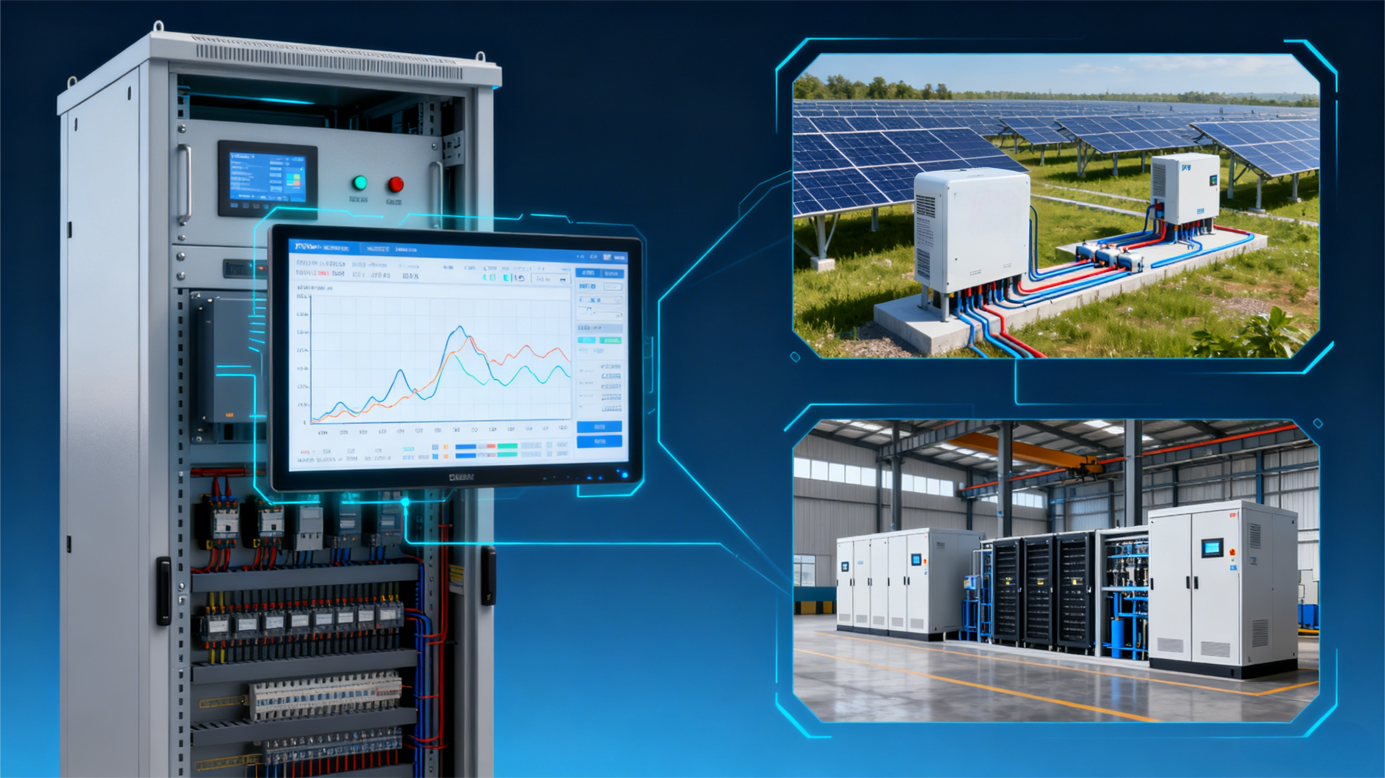
Executive Summary and Performance Testing Context
Modern battery performance test laboratories face increasingly rigorous validation standards for electric vehicle (EV) battery packs, module-level energy storage systems (ESS), and grid-tied Power Conversion Systems (PCS). When evaluating energy storage performance, assessing how test units interact with complex, multi-vector AC grid conditions is a critical safety and compliance requirement. Implementing a high-precision grid simulation power sources system allows performance testing facilities to recreate worldwide AC grid conditions, line disturbances, voltage sags, and frequency fluctuations within a fully controlled laboratory environment.
Deploying heavy-duty performance testing hardware into an automated test line requires meticulous infrastructure planning. Bringing a grid simulation power sources system online demands precise thermal load management, bidirectional energy recovery during discharge, robust digital communication, and strict safety interlocks. In this guide, we detail practical engineering steps to help test engineers achieve seamless integration, optimize laboratory uptime, and uphold international testing standards.
Understanding the Core Role of a Grid Simulation System
At its core, a grid simulation power sources system used in performance test labs is a dedicated, programmable AC simulation system engineered to replicate worldwide utility grid behaviors. Unlike standard power delivery units, this specialized testing system dynamically synthesizes dynamic grid anomalies, including harmonic distortion, phase angle jumps, unbalanced phase voltages, and rapid transient frequency shifts.
In a battery module and pack testing architecture, this grid simulation power sources system serves as the primary AC interface between the facility grid and bidirectional testing equipment. During PCS and pack performance validation, the simulator generates real-world grid disturbances to verify whether protective relays, anti-islanding algorithms, and reactive power compensation functions perform accurately under stress. Furthermore, incorporating energy-regenerative architecture enables performance test labs to feed excess energy back into the facility’s internal grid during battery discharge testing, significantly reducing total operational energy consumption.
Electrical Planning: Capacity, Thermal Dissipation, and Layout
Integrating high-capacity grid simulation hardware begins with thorough facility infrastructure planning. Before positioning high-voltage test equipment, test engineers must conduct a site assessment focusing on three critical parameters: electrical supply capacity, thermal management, and physical cable layout.
First, evaluate your laboratory’s main AC distribution panel. Heavy-duty performance testing setups demand robust circuit protection and adequate short-circuit current ratings (SCCR). Second, thermal dissipation is vital. High-power grid simulators generate substantial operational heat during full-load stress testing. Engineering teams must calculate total thermal loads (BTU/hr or kW) and ensure adequate HVAC cooling infrastructure is operational. Finally, keep cable routing between the grid simulation power sources system and the Unit Under Test (UUT) as compact as possible. Minimizing AC cable length reduces parasitic line inductance, ensuring clean waveform fidelity and preventing signal distortion during rapid transient response tests.
Hardware Setup, Safety Interlocks, and Precision Parameters
Hardware installation requires strict adherence to high-voltage safety standards, such as IEC 61010-1 and NFPA 79. Safe and reliable wiring forms the foundation of an efficient battery performance testing facility.
Begin by establishing an isolated, low-impedance master ground earth (PE) connection. High-frequency switching within the grid simulation power sources system can introduce common-mode noise. Grounding the simulator chassis and test cabinets to a single-point star ground eliminates ground loops and protects high-precision measurement sensors. For high-accuracy evaluation, our performance testing equipment delivers tight output voltage and current regulation, ensuring publication-grade data integrity. Additionally, integrate emergency stop (E-Stop) safety loops directly into the main laboratory control circuit. In the event of a thermal anomaly or over-voltage condition, the integrated E-Stop immediately trips high-voltage contactors, isolating the UUT instantly.
Communication Protocol Integration: Daisy-Chain, CAN, and Modbus Setup
Physical wiring is only part of the integration; real-time digital communication unlocks the full capability of a grid simulation power sources system. Battery performance testing environments rely on automated control software to coordinate battery pack cyclers, environmental chambers, and grid simulators simultaneously.
To ensure reliable, noise-immune data transfer across high-power physical layouts, deploy robust industrial communication protocols. Supported interfaces include Daisy-Chain topology, CAN, RS485, RS232, and Modbus TCP/RTU. In multi-cabinet test systems, a Daisy-Chain or CAN architecture enables microsecond-level signal synchronization across multiple parallel power units. During initial software commissioning, program hardware-level boundary limits—including maximum peak AC voltage and over-current trip points—directly into non-volatile memory to prevent automated scripts from exceeding safe output parameters.
Calibration, Safety Protocols, and International Compliance
Operating high-power performance testing equipment requires structured operational protocols to maintain data accuracy and safety compliance.
Prior to conducting official pack and module performance tests, the grid simulation power sources system should undergo annual calibration against traceable standards, such as ISO/IEC 17025 accredited procedures. High precision in output regulation is essential when certifying energy storage products for international grid-code standards, including IEEE 1547, UL 1741 SA/SB, and IEC 62116. Furthermore, implement a preventive maintenance schedule: inspect cooling filters, verify DC bus capacitor health, check busbar torque specifications, and test safety interlocks regularly. By pairing high-precision testing hardware with rigorous operating procedures, performance test labs can consistently deliver repeatable, high-integrity validation results.
Conclusion and Future-Proofing Your Performance Test Lab
Integrating a grid simulation power sources system into a battery performance test lab provides the capabilities required to bridge laboratory verification and real-world grid conditions. By carefully planning electrical infrastructure, implementing robust industrial communication like CAN and Daisy-Chain, and maintaining high measurement precision, test facilities can achieve exceptional testing versatility. As battery packs and ESS technologies advance toward higher voltages and faster response times, scalable grid simulation equipment ensures your performance test lab remains at the forefront of energy storage verification.
Table of Contents
- Executive Summary and Performance Testing Context
- Understanding the Core Role of a Grid Simulation System
- Electrical Planning: Capacity, Thermal Dissipation, and Layout
- Hardware Setup, Safety Interlocks, and Precision Parameters
- Communication Protocol Integration: Daisy-Chain, CAN, and Modbus Setup
- Calibration, Safety Protocols, and International Compliance
- Conclusion and Future-Proofing Your Performance Test Lab